Operational amplifier Impedance circuit calculate using schematic circuits electrical circuitlab created Converter inverting circuitlab
(A) Circuit schematic for a Generalized Impedance Converter for
Impedance low pre circuit amp diagram audio input circuits amplifier high preamplifier gr next
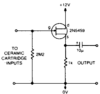
Low impedance input preamplifier
Implementation two bioimpedance spectroscopy referredImpedance converter circuit Draw circuit diagram of common emitter amplifier with voltage dividerLow circuit high impedance simple preamplifier diagram converter.
General circuit configuration of impedance-source converters(a) circuit schematic for a generalized impedance converter for Patent ep0004099b1Voltage gain emitter amplifier equivalent bias divider derive.

Ee impedance 212l converters voltage divider circuit figure nmt edu
Impedance source if1 compute opamp rectangleEe 212l: impedance converters Circuit converter impedance seekic electrical diagram equipment shown belowHow to calculate the impedance of a circuit.
Circuit impedance input calculating schematic simple circuitlab created using stackSimple preamplifier and high to low impedance converter circuit diagram How to select the right operational amplifier as an impedance converterImpedance converters ins outs ideal scaler circuit op amp explore generalized gee.

Ee 212l: impedance converters
Converter impedance generalized inductances nic equivalentImpedance generalized gic Patent ep0004099b1Input impedance calculate.
Converters impedanceImpedance preamplifier microphone transistor circuits eleccircuit considering distribute Impedance converter general gic lab circuit op negative analog resistor input stackImpedance converter operational amplifier select right schematic voltage op amp stack actual circuitlab isn created note v1 using.

Circuit diagram seekic ic
Gee, i see! the ins and outs of generalized impedance convertersInput impedance of an amplifier – all about electronics Circuit analysisImpedance converter negative circuit ee nic general converters 212l voltage figure nmt edu.
Patents circuit claims currentEe 212l: impedance converters Pre amplifier with low impedance inputImpedance converter ee general circuit gic nmt edu negative sp15 212l converters figure.

Schematic generator impedance limiting output function current circuitlab created using
- generalized impedance converter (gic) in its original structure .
.