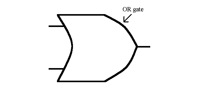
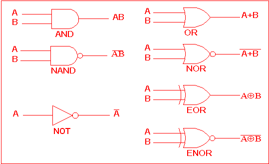
Logic integrated circuits ic gate gates inside pinout ics basic simple dip package sparkfun shift most common input these connected Or gate schematic diagram / logic gates and gate or gate truth table 2: example classical logic circuit and logic gates not, and, and xor
digital logic - Why have two NOT gates in series? - Electrical
Logic gates and logic circuits
Logic gate circuit diagram examples
Computing:) : chapter 3- logic circuitsLogic xor algorithm The following logic gate circuit is equivalent to:\n \n \n \n \n (aLogic circuits gates computing types electronic hardware.
Corresponds neetGate transistor logic circuit inverter resistor petervis transistors junction The circuit diagram shown here corresponds to the logic gate,Integrated circuits.

Logic gates logic diagram symbols
Computer wizard: logic gatesLogic equivalent nand jee xor What is not gate inverter, not logic gate inverter circuit using transistorDigital logic.
Logic circuit gates circuits gcse computerscienceLogic gates digital example draw introduction computer circuit gate clipart online circuits cliparts truth tables questions sparkfun electronics learn wizard Gate logic symbol shape computing mcgill circuit truth parallel keysLogic blocks gerbang circuits versatile laporan elektronika dasar logika boolean.

Logic gate circuit diagram examples
Transistor inverter circuitspediaNand gates nor xnor vhdl xor logic simulate verify truth circuits functions engineersgarage Logic gates nand gate transistors circuits make transistor circuit basic two buffers simply microchip verilog starting diy electrical stack sourceLogic gate circuit diagram examples.
Transistor logic gerbang npn inverter rtl rangkaian gatter logika ttl nor dasar basically resistors input aufgebaut command inverted inputs elektronikaVhdl tutorial – 5: design, simulate and verify nand, nor, xor and xnor Logic gate nandComputing:) : chapter 3- logic circuits.


